- Detail
- Parameters
- Review
1, The Principle of Constant Velocity Transmission
As figure 1, two shafts intersect in a plane. Point 0 is the intersecting point of the two axes. Point P is the intersecting point of the two verticals through O towards the two axes (the transmitting point of the force).The verticals from P to the axes are w1 and w2.The angular velocities of the two shafts are co i and co 2.The peripheral velocity of Point P is w 1 • R1 and w 2 • R2. Point P is the common point of the two shafts.
So,w1 • R1= w2 • R2.
If the drived shaft and the driving shaft are required to rotate at the same angular velocity(w1 = w2 ) , thus .the lengths of the two verticals intersecting at Point P are equal ( R1 = R2).Point P is always in the same plane together with the two shafts, line PO equally divides the angle included between the two axes.
Based on this principle, the center of the steel balls (the intersecting point and the force transmitting point) of the constant velocity universal joint designed by us is always located on the line which is included between the two shafts and equally divides the angle included between the two axes. This can assure the constant velocity torque transmission of the joints.

Figure 1
2, The mechanical resonance
For Hooke Couplings, its two joints must be assembled on an intermediate shaft if the constant velocity transmission is required .These two joints must be parallel or share a common plane and have an equal angle .Mechanical resonance would occur due to the changes of the angular velocity and the torque of the intermediate shaft at large operating angle and high rotary speed.
Our ball cage constant velocity joint can assure high quality constant velocity transmission even if it is used individually. Its changes of the angular velocity and torque are small. Thus the amplitude and noise of the mechanical resonance can be decreased. The smooth operation of the joints can be assured.
3, The additional bending torque
For a universal joint linking two intersecting shafts, some additional bending torque on the driving shaft and the drived shaft would occur due to the change of operating angle and torque when it transmits torque. The additional bending torque and the position of the intersecting angle for the Hooke Coupling would change in one phase of the rotation.
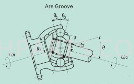
But for the ball cage universal joint, its intersecting point is always located on the equally divided crossing angle line of the shafts due to its structural characteristic. The value and direction of its additional bending torque would keep unchanged. Its value of the additional bending torque is only half of that of the Hooke Coupling (as figure 2).
The additional bending torque of the Hooke Coupling M = T • tan 6
The additional bending torque Of the ball cage universal joint M = T • tan 0/2
Figure 2
4, Flexible disposition
Hooke Coupling consists of two joints with an intermediate shaft. They are disposed parallelly or share one common plane and have an equal angle so that the torque can be transmitted at constant velocity. In other word, the disposition of constant velocity transmission must be in accordance with the necessary condition ,that is 0 i =0 2 (as figure 3). As for the ball cage constant velocity universal joint produced by us ,the linking of two intersecting shafts can use one universal joint .It can be used at random angle in three-dimension space, that is. 00 2 (as figure 4).The space and cost can be reduced.So,Our ball cage
constant velocity universal joint is an ideal choice when the space is limited and the excellent characteristic of
constant velocity is needed.
Figure 3 & Figure 4
5,Structure type
There are two types of our ball cage constant velocity universal joints: fixed and sliding types.
5.1, fixed ball cage constant velocity universal joint (its second name is arc groove universal joint)
As figure 5. the tracks for the balls rolling along the axial direction are located on the circles of the inner and outer races. The steel balls are kept within the tracks by the cage windows. Torque is transmitted through inner race, steel balls and outer race (figure 7).The arc ball tracks extend axially. The steel balls are distributed within the equally divided angle plane of the two axes. The inner race, outer race and the fitting surface of the cage configurate as concentric spherical profile. The inner race .outer race and the cage move separately to keep the steel balls in the right positions and moving smoothly when the operating angle changes.
5.2,Sliding ball cage constant velocity universal joint (its second name is straight groove universal joint)
As figure 5,the generatrix of the inner and outer tracks is parallel to the axis of the inner and outer races.The inner aperture of the outer race is a cylindric surface.The inner race, cage and steel balls can slide axially in the outer race in operation .The sliding friction is small. It specially suits for the working situation of torque transmission and frequent expansions.