- Detail
- Parameters
- Review
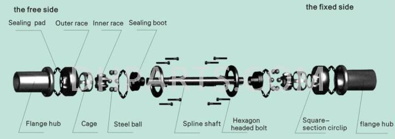
The structure of the ball cage constant velocity universal joint
6, The characteristic of the arc groove universal joint
6.1,The axial section profile of the steel ball track of the universal joint is arc.
6.2.The adjustment of the installation distance and axial expansion can be done through the sliding spline fit in the universal joint. The structure of the joint can be more compact.
6.3,The designing and processing of the universal joint take the rotary center as the basis. Then higher dynamic balance accuracy can be reached to satisfy the demand of high speed operation.
6.4.The two universal joints are linked through the intermediate spline fit. The larger axial expansion in specific operation location can be satisfied.

7, The characteristic of the straight groove universal joint
7.1,The axial section profile of the steel ball track of the universal joint is straight.
7.2,The inner race and the driving shaft are processed as a common body. Greater torque transmission can be done than that with the sliding spline fit linking in the universal joint.
7.3,The adjustment of the installation distances and axial expansion can be done through the sliding track in the universal joint .The structure of the joint can be more compact.
7.4,The designing and processing of the universal joint take the rotary center as the basis. Then higher dynamic balance accuracy can be reached to satisfy the demand of high speed operation.
The torque calculation of the ball cage constant velocity universal joint
The procedure of the type selection
Generally, the ball cage constant velocity universal joint consists of two universal joints and an intermediate shaft. It can be used both in planar system and space system.
The structure and specifications of the ball cage constant velocity universal joint can be selected according to the toad, operating rotary speed .operating angle and calculated torque.

Torque calculation
Tc=9549
K1K2K4 P/K3 n≦Tn
Tc—The calculated torque of the joint ( N • m )
Tn—The nominal torque of the joint ( N • m )
P—Driving power ( kW ) n—Operating rotary speed (r/min )
Ki—Power generating machine factor. It can be accessed from Table K2—Continuous working time factor, It can be accessed from Table 2 K3~Operating angle factor, it can be accessed from Table 3 K4—Life time factor, It can be accessed from Table 4

